Transceiver Testing
Family of RF test systems designed for transceiver testing. Radio-to-radio testing in a closed mesh network. Step attenuators allow you to dynamically fade up/down the RF signal between radios. The difference between the three system types is the fan-out between radios.
Full Fan-out Transceiver Test Systems
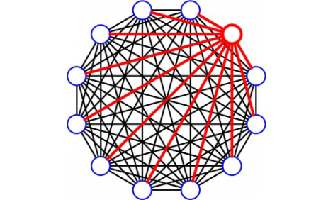
A full fan-out transceiver test system is constructed as a fully meshed matrix. There is a path between every pair of ports. Each path has its own individually controlled programmable attenuator. Each port can be connected to a device that can transmit/receive signals (i.e. radios, handsets). The programmable attenuators allow for a different dB setting for every path through the matrix. The attenuators can have their dB setting faded over a time interval to simulate signal fading between radios. The example diagram shown is a 12 port full fan-out configuration. This 12 port design will have a total of 66 programmable attenuators.
Limited Fan-out Transceiver Test Systems
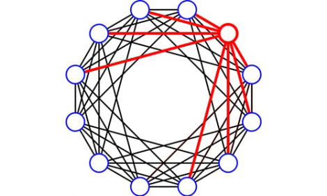
For a limited fan-out transceiver, a port connects to only X number of its neighboring ports. The number of its neighboring ports can vary depending on the application. The example diagram shows a 12 port LC8 design. Each port is connected to only its 8 closest neighboring ports (4 upper neighboring ports & 4 lower neighboring ports). This design requires only 48 programmable attenuators.
This limited fan-out design is most useful for reducing size/cost of designs with a large number of ports. For example, a full fan-out 48 port design would require 1128 programmable attenuators. A limited fan-out 48 port LC16 requires only 384 programmable attenuators. Cost and size reduction of approximately 66%.
Hub Fan-out Transceiver Test Systems
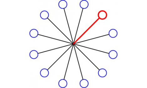
The hub fan-out transceiver test systems are constructed as a star matrix with a programmable attenuator on each port. The star configuration limits the number of paths in the matrix to be equal to the number of ports. The star design results in a lower cost due to the lower number of programmable attenuators.
The example diagram shown is a 12 port hub fan-out configuration. All ports are connected via a resistive power divider/combiner with a star configuration. There are a total of 12 programmable attenuators.
Functionality Vs. Cost
For a transceiver test system, the major cost driver is the number of internal step attenuators. Each of the three types of transceiver test systems we offer require different numbers of internal step attenuators. This difference is due to the way the radio-to-radio connections are created. The full fan-out type has the highest number of internal step attenuators. The hub fan-out type has the lowest number of step attenuators.


